oversampling?

User avatar
utdgrant
Posts: 541
Joined: Wed Apr 07, 2021 8:58 am
Location: Scotland
Contact:

Re: oversampling?

Post by utdgrant »

ColinP wrote: Mon Dec 18, 2023 2:06 pm L is the result of lerping between A and B and is obviously not bandlimited.
If you calculated M, N, P and Q as the Lerped midpoints between B and C, C and D, D and E, and E and F, then the resulting signal would be both bandlimited and low-pass / comb-filtered.

(With the caveat that f remains fixed at 0.5 throughout)

You can't take one sample pair in isolation and state that the single point output is "not bandlimited". You have to extend the sequence to give that single point context.
BandlimitedSignalf0.5.jpg
BandlimitedSignalf0.5.jpg (468.16 KiB) Viewed 47426 times
______________________
Dome Music Technologies
ColinP
Posts: 952
Joined: Mon Aug 03, 2020 7:46 pm

Re: oversampling?

Post by ColinP »

Grant, I think I can see through the alphabet soup to understand your point.

I'm using an illustration using three samples not two. If we are upsampling by a factor of two using lerping with f = 0.5 then the A, L, B samples in my sketch would indeed be the sequence of samples produced. By definition of what lerping is, it's a straight line. And given that we are talking about a signal extremely close to Nyquist how exactly can a three sample straight line (sampling at an effective rate above Nyquist) be bandlimited? Unless we are looking at DC.

I thought you had already tacitly acknowledged my basic argument when you said...
Remember that linear interpolation will always produce a value somewhere between the two surrounding sample values. This is in contrast to an analogue reconstruction filter. It will 'draw' the only possible waveform which fits through the replayed sample points, even if that means exceeding the voltage represented by two consecutive sample points.
I see you are again presenting a spectrum as evidence and it's the best evidence I've seen as I think all the logical arguments presented so far fail.

I couldn't get SPAN to work last time I tried even though it worked fine previously. I should perhap dust it off and give it another go. But given that the behaviour I'm talking about is extremely close to Nyquist and the spectrum analyser is taking samples at the same sample rate then the data should be taken with a large pinch of salt. I'm pretty sure that it's not theoretically possible for a spectrum analyser to be capable of meaningful analysis at its own Nyquist point.

Experimental evidence needs to be treated with care, we need a good understanding of the theoretical framework and not be just looking for confirmation. Some historical science has been superceded as theoretical frameworks change and people have learnt how to design more discriminating experiments. I believe it's a serious philosophical problem as expermental data can only be understood if we already know about what the experiment is seeking to elucidate. A sort of Catch 22.

My standard example is someone who checks what day it is once a week. They can become ever more certain that every day is Monday as this is exactly what the experimental data reliably indicates.
ColinP
Posts: 952
Joined: Mon Aug 03, 2020 7:46 pm

Re: oversampling?

Post by ColinP »

Just to clarify - an example of upsampling a near Nyquist signal by a factor of two would be pitch shifting a 23.9 kHz sine wave down an octave in GS.

Now I think the result should be within the test range of a spectrum analyser. So if there isn't any aliasing visible in this situation then my argument is faulty. But your spectral evidence so far has been just a sinewave of around 18 kHz mixed with a one sample delayed copy. Which I wouldn't expect to exhibit the problem I am positing because all you are doing is looking at L in isolation rather than A,L,B in sequence.

I'll try and get SPAN working again later today as this is beginning to bug me!
ColinP
Posts: 952
Joined: Mon Aug 03, 2020 7:46 pm

Re: oversampling?

Post by ColinP »

I managed to get SPAN working and I see it sensibly doesn't attempt to analyse above 20 kHz. So I'm using a test sinewave at about 17 kHz. The aliasing caused by lerping would be stronger as we got closer to Nyquist but the results are good enough to offer very strong evidence that my argument is correct.

With no pitch shifting (therefore no fractional buffer access) there is no aliasing as expected...

noshift.png
noshift.png (226.93 KiB) Viewed 47304 times

With -12 semitone shifting (the case my scribble shows) there is a single sideband visible...

minus12.png
minus12.png (190.81 KiB) Viewed 47304 times

With a -13 semitone shift we see serious aliasing...

minus13.png
minus13.png (243.32 KiB) Viewed 47304 times
User avatar
utdgrant
Posts: 541
Joined: Wed Apr 07, 2021 8:58 am
Location: Scotland
Contact:

Re: oversampling?

Post by utdgrant »

ColinP wrote: Mon Dec 18, 2023 6:54 pm I'm using an illustration using three samples not two. If we are upsampling by a factor of two using lerping with f = 0.5 then the A, L, B samples in my sketch would indeed be the sequence of samples produced. By definition of what lerping is, it's a straight line. And given that we are talking about a signal extremely close to Nyquist how exactly can a three sample straight line (sampling at an effective rate above Nyquist) be bandlimited?
Ahhhh, my unreserved apologies. I misinterpreted your diagram (exactly in the way you described).

Yes, the upsampling (my emphasis above) case will not be bandlimited. Lerping is indeed a poor solution for changing replay rates (samplers, pitch-shifters, etc). Using Zeit as a pitch-shifter can lead to some pretty horrendous-looking spectra and audible nastiness. Good enough for simulating Vogons and Chipmunks, not so great for simulating parallel fifths on a Juno 6.

OTOH, Lerping is definitely 'good enough' for implementing fractional delays of fixed length (or gradually changing length, as when modulated by an sub-audio LFO). Zeit as chorus unit, flanger or resonant waveguide sounds pretty decent in all but the most critical-listening situations.
______________________
Dome Music Technologies
ColinP
Posts: 952
Joined: Mon Aug 03, 2020 7:46 pm

Re: oversampling?

Post by ColinP »

Absolutely no need for apologies Grant. It's my fault for not expounding my reasoning with greater clarity.

However, having paraded GS's dirty laundry in public I'm going to have to attempt to fix the problem at some point in the future. I stand by my opinion that lerped fractional buffer access is "good enough" and that the vast majority of people probably can't hear moderate aliasing on one track in a larger mix but I think it should be a relatively easy job to add the x8 or x16 pre-upsampling I mentioned earlier and I think that should reduce the aliasing considerably.

I've given a little more thought to the performance impact this will have due to L2 and L3 cache misses and have come to the conclusion that it's too complex to analyse and will vary considerably between architectures. So I'll have to implement it to see the true cost. By default I'll leave the pre-upsampling off so it won't impact legacy patches but the option might be welcomed by those people who are extra sensitive to aliasing (and perhaps have top-end machines with massive L3 caches and DDR5).

This isn't going to happen in the near future though as I'm still knee deep in developing Adroit Custom. I'm about 3/4 way through a 5th rewrite so it's probably going to be the end of Feb before I'm done.
User avatar
ChR_is
Posts: 107
Joined: Wed Sep 22, 2021 5:48 pm

Re: oversampling?

Post by ChR_is »

i see we're still talking about different things.

LERPing itself, linear interpolation to be clear, will not produce aliasing. it simply can't. it's a linear process. if you read from a buffer with constant distance/at the same point per sample, there won't be any added harmonics and therefore no aliasing. you'll only get the lowpassing effect. we can even see that in the example you posted. when no pitch shift is active and the buffer is read at constant speed, no sidebands are produced/present in the spectrum.
ColinP wrote: Tue Dec 19, 2023 12:39 pm With no pitch shifting (therefore no fractional buffer access) there is no aliasing as expected...


noshift.png (226.93 KiB) Viewed 129 times
once you start reading from the buffer at a different rate and therefore change the sample point in the buffer irregularly there's aliasing. this is because you are now treating the interpolated buffer no longer as a buffer, but as a signal itself. since lerping is not continuous the produced spectrum will be endless and therefore alias.
ColinP wrote: Tue Dec 19, 2023 12:39 pm With a -13 semitone shift we see serious aliasing...


minus13.png (243.32 KiB) Viewed 129 times
what also happens here is that you are effectively phase modulating the signal (oversimplified of course). there's also a lot more to be considered in a granular processor that could affect this like the window, the rate, overlaps, etc..

the same "lerping issues" also apply to a chorus or a flanger, but it does not apply to a static delay. and that was the whole point of the discussion. you can apply a higher order interpolation but that'll sacrifice more high-end content. you could also try your luck with allpass interpolation which might behave better frequency wise but won't react as nicely to modulation as other forms of interpolation. pick your poison.

now why's there a lowpassing effect? it's simply in the nature of interpolation. interpolation is always averaging. and put very simple, a lowpass filter is also averaging. you simple ignore all values that might be between two samples and act as if there was a straight line. that'll get rid of some of the frequency information that's between the samples. think about it this way. what happens if you broaden the spacing? LERP over 2 samples? 4 samples? 100 samples? in essence you are "smoothing" out the signal which, again, is averaging and therefore filtering.
User avatar
ChR_is
Posts: 107
Joined: Wed Sep 22, 2021 5:48 pm

Re: oversampling?

Post by ChR_is »

you don't even need to trust or believe me. there's been extensive research already ;)
i can recommend this paper in particular: http://yehar.com/blog/wp-content/upload ... 8/deip.pdf
in this paper the many interpolation methods are evaluated in the audio context. specifically their frequency response.
ColinP
Posts: 952
Joined: Mon Aug 03, 2020 7:46 pm

Re: oversampling?

Post by ColinP »

Thanks for the link Chris. Rather than a research paper, it's a dense 63 page student essay from twenty odd years ago that contains no references but that doesn't mean it's not valuable so I'll check it out when I have a little more time.

I'm struggling with some of your comments. I'm reasonably confident that fractional buffer access using lerping can produce non-bandlimited signals as I think I've shown this to be the case from both a theoretical and experimental POV. I've also addressed why it's pretty daft to view this through the lens of low-pass filtering given that when f = 0 or f = 1 it certainly isn't and in most other circumstances f jumps about all over the place so the frequency response alters sample by sample. OK one could argue that it's filtering Jim, but not as we know it...

https://youtu.be/FCARADb9asE?si=tIgkTsIObEtU6gYr

You are right about there being various factors in a granular setup that could affect results so here's an image of the test patch. I'd post a .voltagepreset file but VM doesn't handle paths to VSTs very well so it would only work for some. Anyway the patch is pretty easy to construct.

The GS settings are intended to be as neutral as possible, turn the RATE down, the SIZE up and set the OMDU switch to O to disable the arpeggiator. The GS free demo period is 30 days (EDIT: correction 14 days, I was thinking of the LSSP demo period) so you can experiment without cost or a rapidly looming deadline.

One needs to hit the GS RECORD button to record the test signal for a while before hitting the SYNTH button and tweeking the PITCH knob.

People as old as me probably won't be able to hear the 17 kHz sinewave BTW.

lerpTest.png
lerpTest.png (891.04 KiB) Viewed 47164 times
Last edited by ColinP on Thu Dec 28, 2023 6:47 pm, edited 4 times in total.
User avatar
utdgrant
Posts: 541
Joined: Wed Apr 07, 2021 8:58 am
Location: Scotland
Contact:

Re: oversampling?

Post by utdgrant »

Here's a very straightforward experiment anyone can do in Audacity.

1. Set your project sample rate to 48 kHz.
2. Generate a sine tone at 21,345 Hz for one second duration. If you zoom in to sample resolution on the lollipop display of the waveform, it is all over the place, looking nothing like a smooth sine wave.
3. Copy and paste the generated sine wave to another track, removing the first very first sample. This second track represents samples at t=1, 2, 3, 4, etc. The original track represents samples at t=0, 1, 2, 3, etc. Both of these tracks are completely band-limited.
4. Mix both tracks at 50:50 amplitudes to a third track. This creates a Lerped version of the first waveform, with a resulting sample exactly half-way between t=0 and t=1, t=1 and t=2, t=2 and t=3, etc. This resultant track is still band-limited, because both source tracks were band-limited and they were just added to each other in a linear way.
5. Notice that because the sine wave is very close to Nyquist, the comb-filtering effect has come into play and the amplitude of the mixed track is very much lower than either original track.
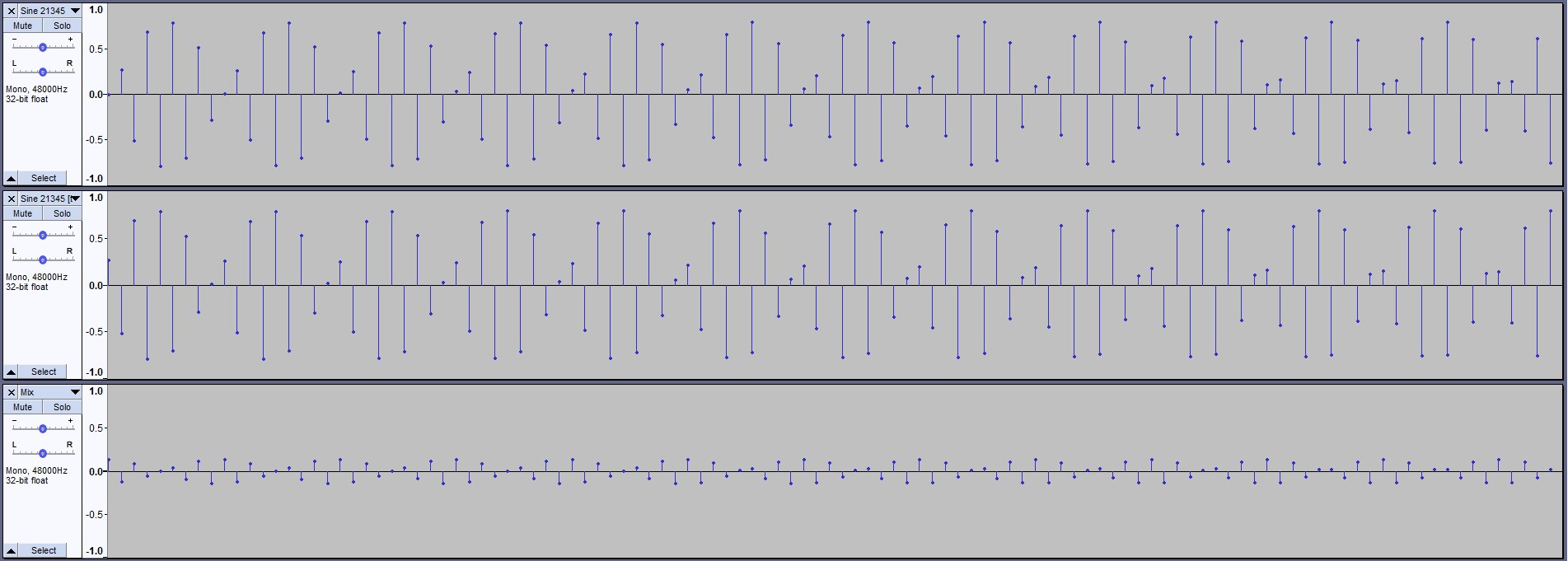
Lerping1.jpg
Lerping1.jpg (150.5 KiB) Viewed 47152 times
6. Copy the mixed track to a new track and boost the amplitude so that its peak value is something like -0.5 dB.
7. Resample the entire project up to 192kHz (i.e. x4 oversampling). Audacity uses a fancy algorithm for upsampling which somehow restores the chaotic-loooking original generated waveforms to smooth sine waves. Note that no extra information has been added. All these upsampled point values have been calculated exclusively from the garbled 21,345 Hz sine wave sampled at 48 kHz.
8. Note also, that the two original tracks appear to be almost 180 degrees out-of-phase with each other, which accounts for the destructive interference and the low amplitude of the mixed signal.
9. Note also, (also) that the mixed signal (and the amplified mixed signal) appears to be phase-shifted by about 90 degrees relative to both source signals. Or, looked at another way, the peaks in the mixed signal fall between the peaks in the two original waveforms.
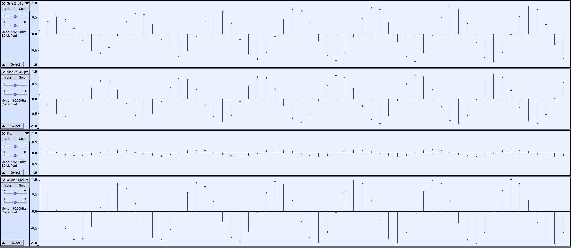
Lerping2.jpg
Lerping2.jpg (163.67 KiB) Viewed 47152 times
10. If we perform a spectrum analysis of the mixed, amplified signal, we get a nice clean sine wave at 21,345 Hz. The tails are due to the Rectangular Window method and do not imply broadband noise.
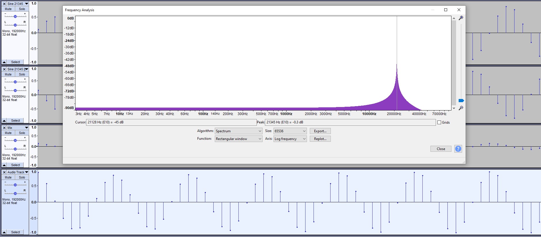
Lerping3.jpg
Lerping3.jpg (179.78 KiB) Viewed 47152 times
I THINK this is what Chris has been talking about for the past few pages :) . We're advancing through the buffer(s) at a rate of one playback sample per one recorded sample (no upsampling or downsampling, no freq shift). The mix ratio is always 50:50 so the effective fractional delay is always 0.5. Therefore, the resultant waveform is always the arithmetic midpoint between sample[t] and sample[t-1] (or between sample[t] and sample[t+1] depending on how you want to look at it). When we examine the mixed waveform (made up of all midpoints and none of the original end points), we are still left with a band-limited sine wave. Albeit, it has undergone a phase-shift and a reduction in amplitude. Lower frequency sine waves are hardly touched by either of these effects. If you want to see it for yourself, this is left as an exercise for the reader! :lol:
______________________
Dome Music Technologies
Post Reply

Return to “Module Designer”