Page 1 of 2
DC Offset
Posted: Tue Apr 26, 2022 2:35 pm
by ColinP
I encountered a serious clipping problem in a patch today that took some time to debug.
Well, it's not actually a bug but something to be aware of in certain patches with modules that can't cope with large DC offsets added to their audio inputs.
Here's a test rig that shows the effect...
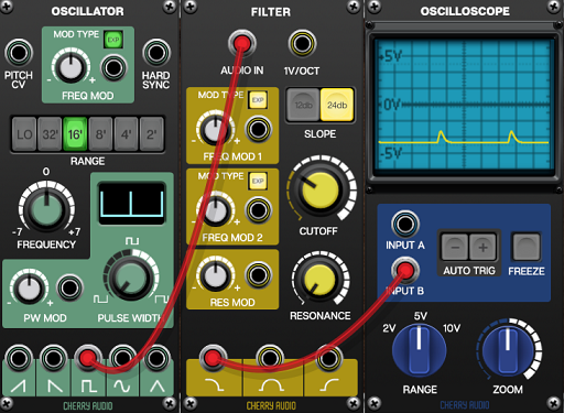
- pulseDCoffset.png (247.52 KiB) Viewed 30097 times
It's caused when a pulse wave is low-pass filtered. As you can see, one can end up with a huge DC offset.
The solution is to apply a high-pass filter with a low as possible cut-off frequency after the low-pass filter.
Re: DC Offset
Posted: Tue Apr 26, 2022 3:03 pm
by huggermugger
Interesting, and good catch! Even dropping the HPF cutoff to 0 Hz makes the difference.
Re: DC Offset
Posted: Tue Apr 26, 2022 9:06 pm
by utdgrant
You do have to be careful in this situation, though.
Effectively, once you've fed the output of the LPF into the HPF, the pulse wave is spending its low period just below 0V, but its brief high period will shoot up to nearly 10V. This is fine when the LPF is limiting the slew rate so it never reaches 10V. However, if you should raise the cutoff freq of the LPF, the peak voltage will break through and exceed 5V, leading to other potential clipping situations down the line.
If you attenuate the LPF output to 50% before feeding it to the HPF, you can guarantee to stay within the 'safe' limits of +/- 5V.
On a slight tangent, I don't believe the CA filter does actually get down to 0Hz, despite what the cutoff knob says.
Not to blow my own trumpet, but the Smol Rat goes waaaaaaaaay lower than it!

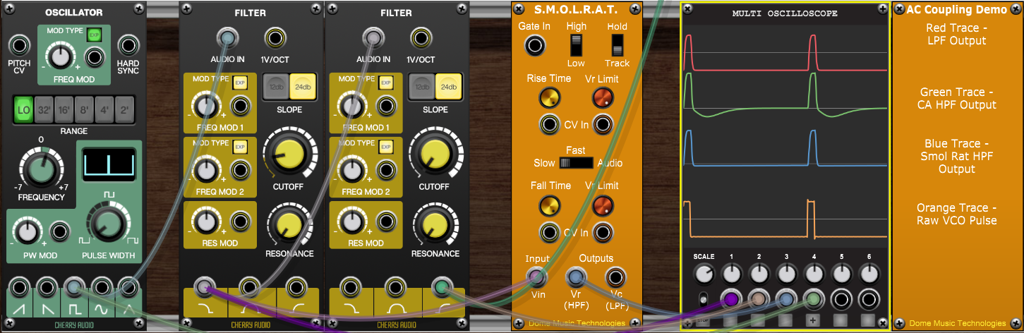
- SmolRatDCOffset.png (616.96 KiB) Viewed 30076 times
Re: DC Offset
Posted: Wed Apr 27, 2022 7:52 am
by honki-bobo
It's not a bug, it's a feature... seriously!
Mathematically speaking, a LPF is basically performing a weighted moving average of a given number of samples. When you're feeding it a square wave with a pulse width of nearly 0% you're basically left with mostly samples of -5V, thus leaving you with mostly (close to) -5V at the output. If you crank up the pulse width to nearly 100% you will notice the output of the LPF moves towards 5V.
Speaking in terms of frequency, a DC offset is a signal of 0 Hz. This is why you can remove it by passing the signal through a HPF.
If the filter does not introduce resonance/feedback (or amplification, which it shouldn't), the output of the filter should also not exceed the voltage range of the input signal.
Re: DC Offset
Posted: Wed Apr 27, 2022 5:47 pm
by seal58
A solution is on the way. I created a module, which can remove DC part of a signal without changing signal itself. That module waits for approvement.
Re: DC Offset
Posted: Wed Apr 27, 2022 6:03 pm
by MRBarton
Just a quick note. VM doesn't have a "safe zone" within a patch and will quite happily process trillion volt signals (without arcing). The only place that matters in this regard is the output signal back into the world, and if you exceed 5v there, just turn it down.
Re: DC Offset
Posted: Thu Apr 28, 2022 6:02 am
by utdgrant
MRBarton wrote: ↑Wed Apr 27, 2022 6:03 pm
Just a quick note. VM doesn't have a "safe zone" within a patch and will quite happily process trillion volt signals (without arcing). The only place that matters in this regard is the output signal back into the world, and if you exceed 5v there, just turn it down.
Good to know. Many thanks!
Re: DC Offset
Posted: Sat Apr 30, 2022 6:44 pm
by ColinP
MRBarton wrote: ↑Wed Apr 27, 2022 6:03 pm
Just a quick note. VM doesn't have a "safe zone" within a patch and will quite happily process trillion volt signals (without arcing). The only place that matters in this regard is the output signal back into the world, and if you exceed 5v there, just turn it down.
You are right at a theoretical level but in practice signal levels can be critical in all kinds of situations beyond just the final outputs.
Anything that involves envelope following for instance. Or modules that do wave folding, saturation or distortion. Or doing something like FM when there's an unexpected 3V bias to the modulation.
Re: DC Offset
Posted: Sat Jun 11, 2022 3:56 pm
by utdgrant
ColinP wrote: ↑Sat Apr 30, 2022 6:44 pm
Or modules that do wave folding, saturation or distortion.
I was checking out the differences in operation of some low-pass filters today. I was quite surprised at how quickly the VM904a started to go into saturation. The output appears to be clamped to +/- 5V.
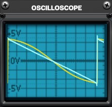
Input is standard CA Oscillator on sawtooth wave (+/-5V) attenuated to various levels:
Attenuation at 32%:
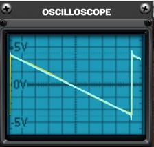
- 904at32percent.jpg (14.9 KiB) Viewed 29676 times
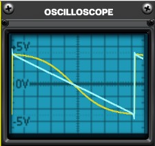
Attenuation at 50%:
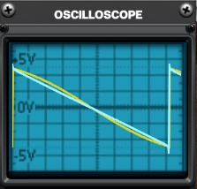
- 904at50percent.jpg (15.39 KiB) Viewed 29676 times
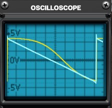
Attenuation at 75%:
- 904at75percent.jpg (15.03 KiB) Viewed 29676 times
to be continued (due to number of attachments allowed)...
Re: DC Offset
Posted: Sat Jun 11, 2022 4:03 pm
by utdgrant
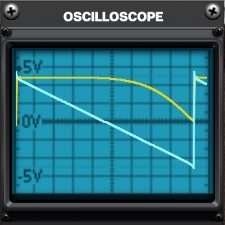
Attenuation at 100%:
- 904at100percent.jpg (15.73 KiB) Viewed 29676 times
Whilst the saturation is symmetrical around 0V, when you add a DC offset to the input, the output becomes asymmetrical:
Attenuation at 100%, +1V DC offset at input:
- 904at100percentPlus1VoltDC.jpg (15.17 KiB) Viewed 29676 times
Attenuation at 100%, +3.9V DC offset at input:
- 904at100percentPlus3.9VoltDC.jpg (15.97 KiB) Viewed 29676 times
As you can see, the output becomes unipolar with a +3.9V DC offset at the input.
I'm not complaining about it, though!
Just making an observation about possible knock-on effects from DC offsets before getting to the output stage.